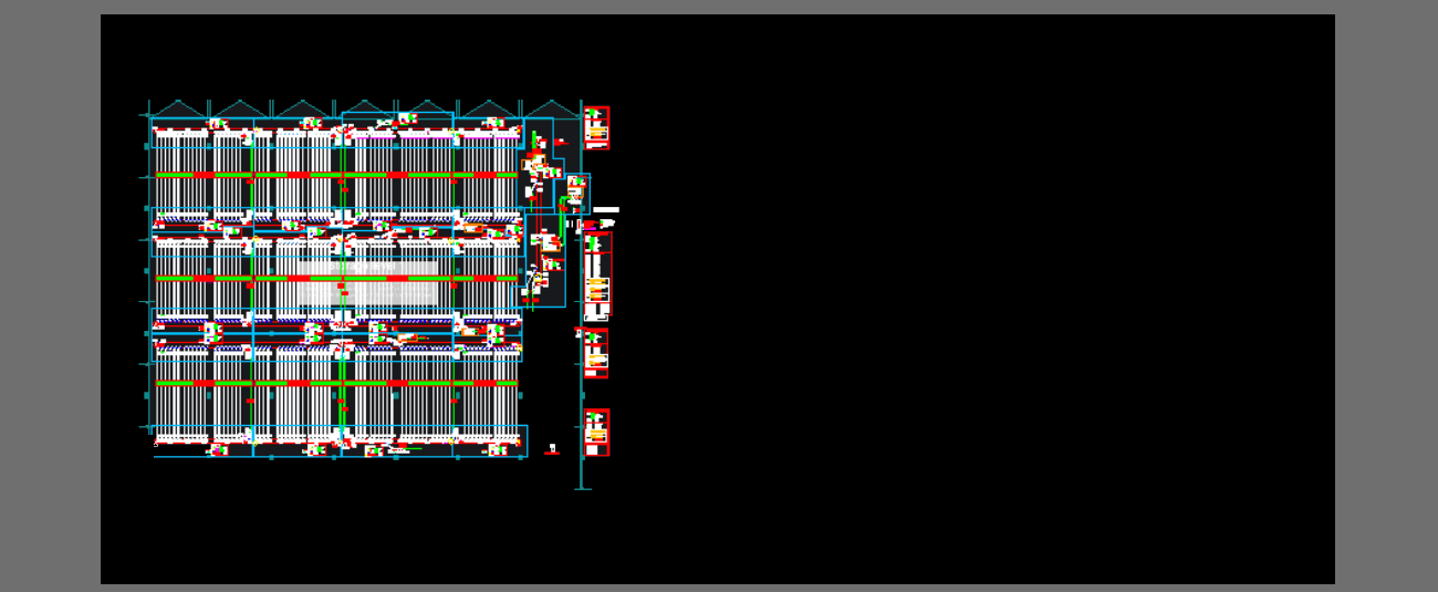
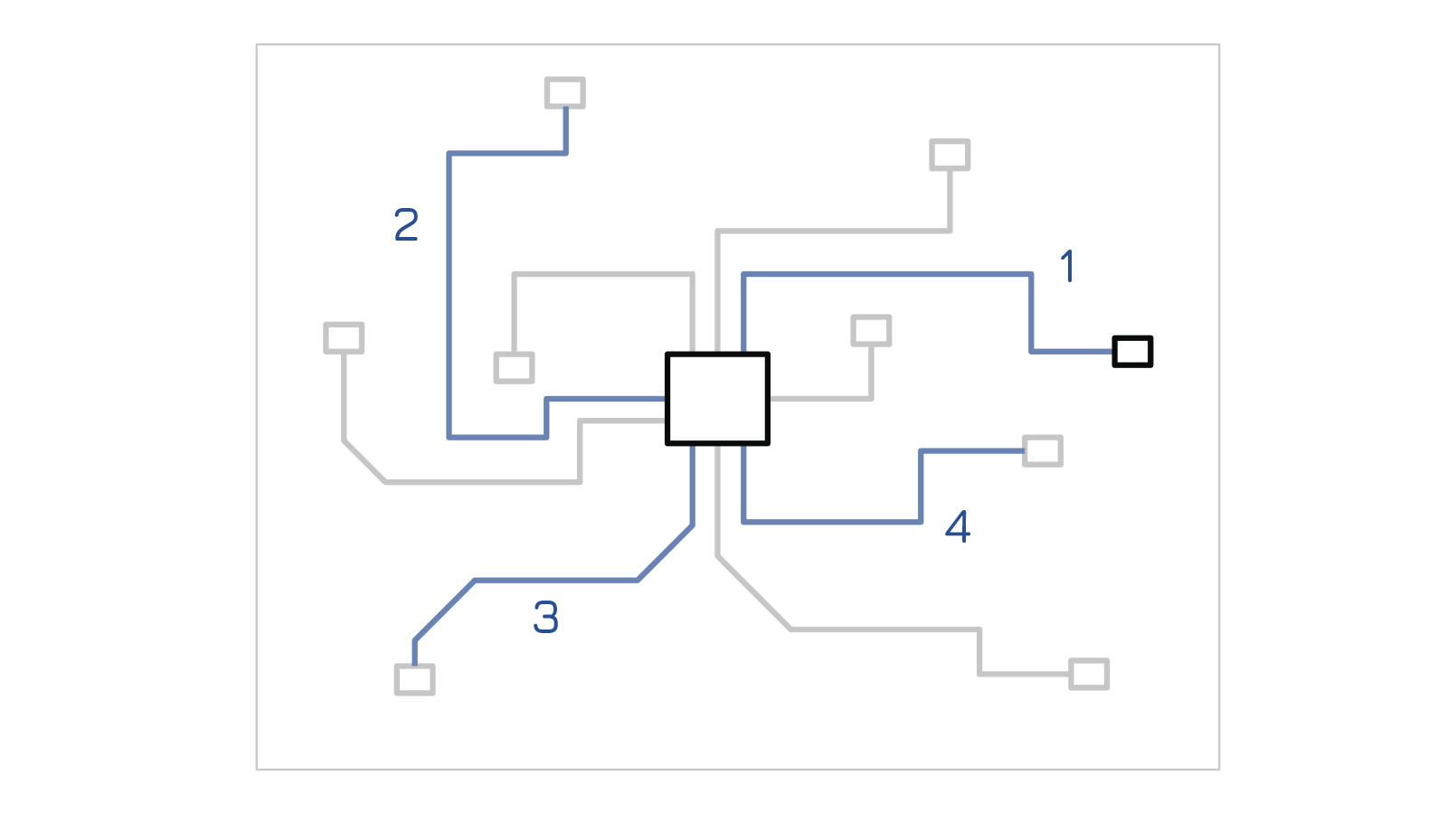
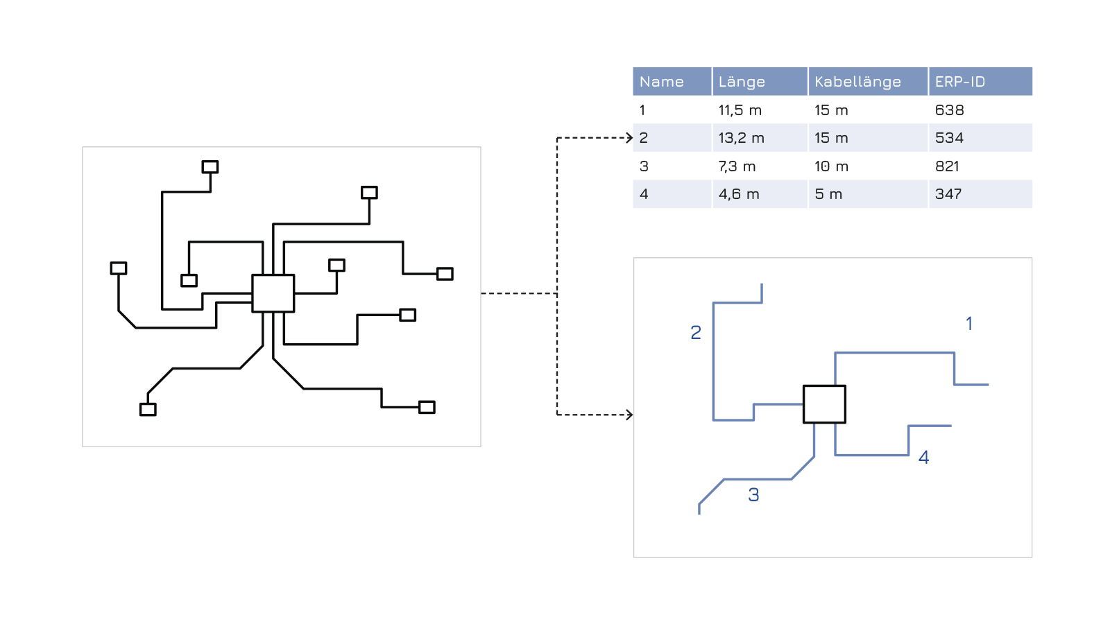
Overview: Cable trays, sensors and actuators in a plant
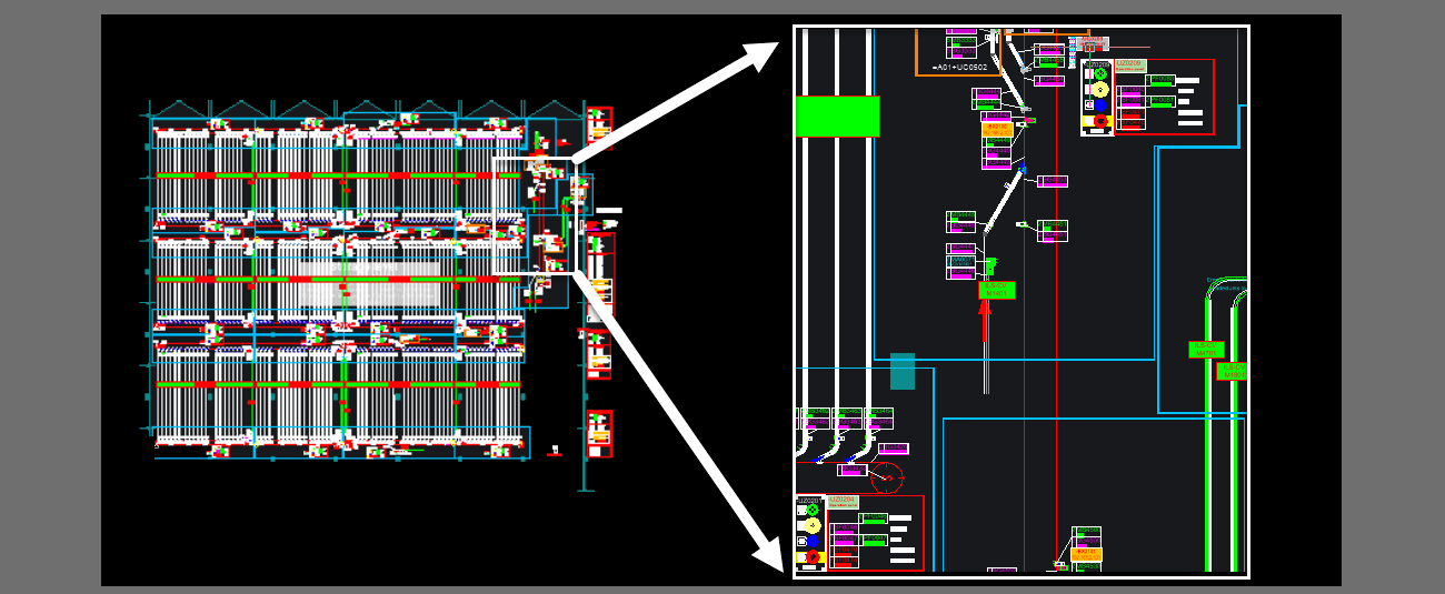
Excerpt from the plant: A group of symbols
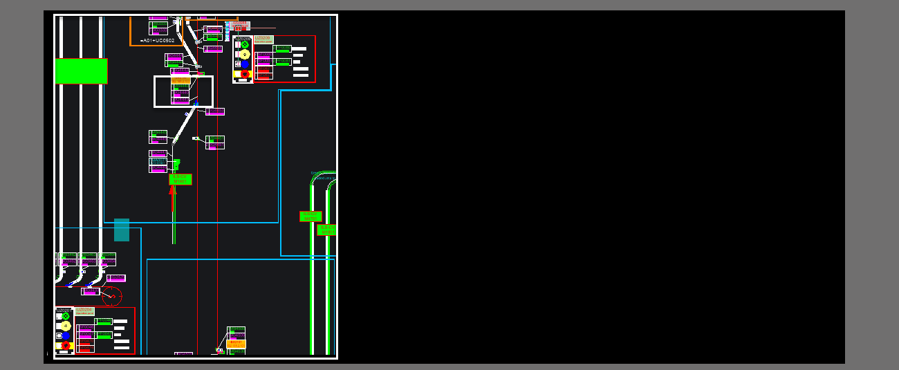
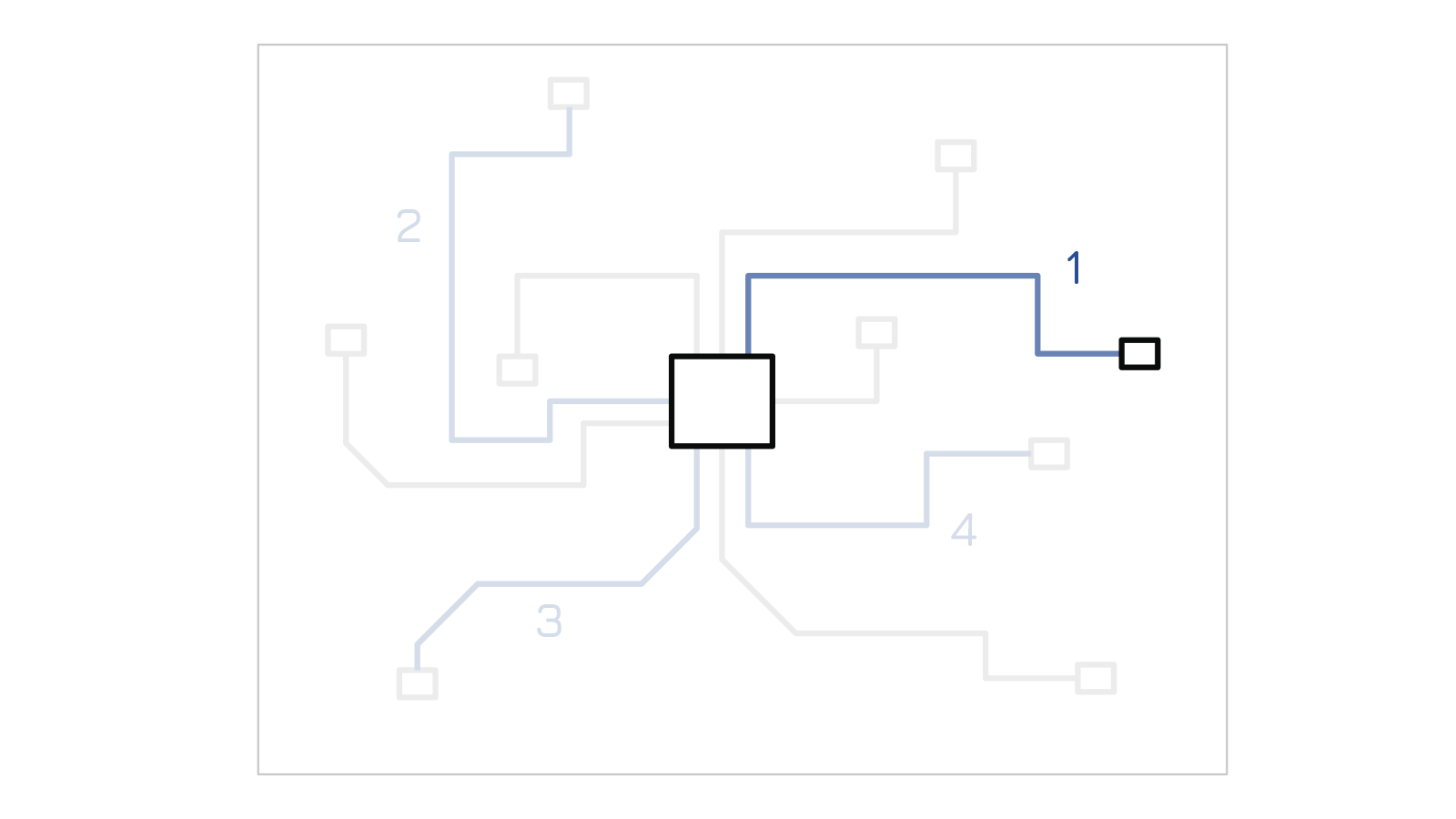
Excerpt from the group: Some symbols
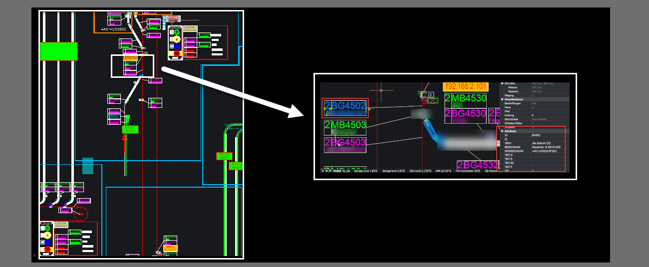
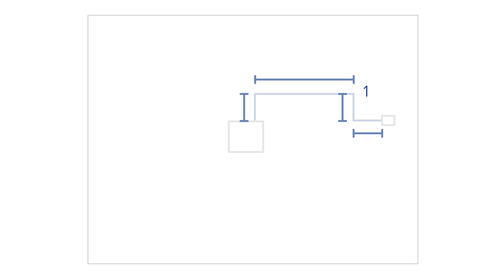
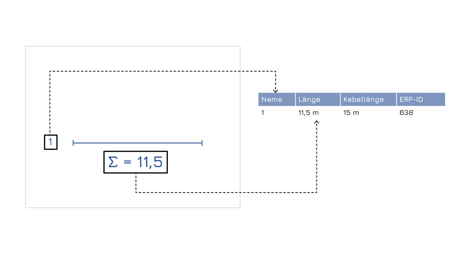
Example of a symbol

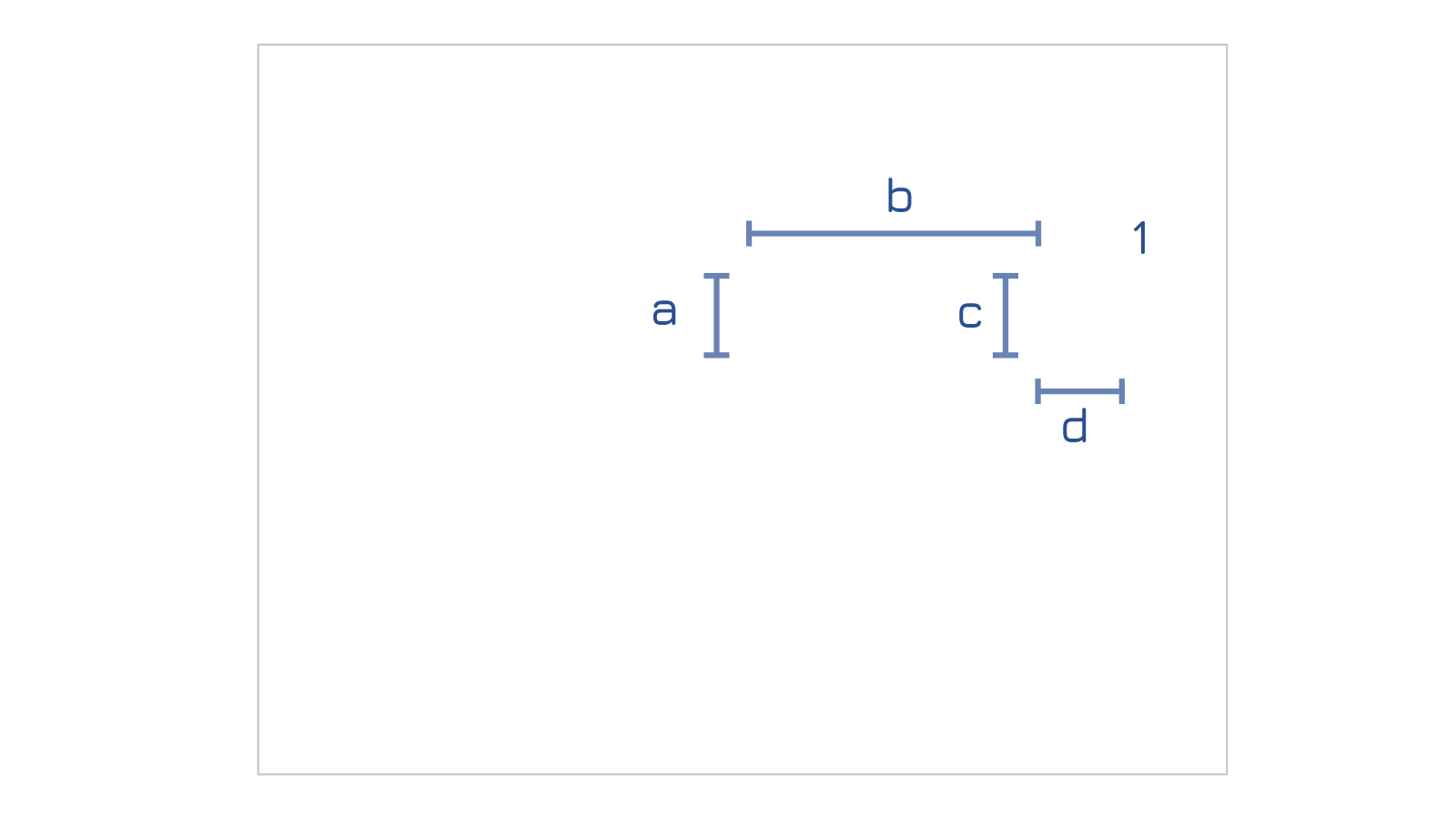
A symbol and its attributes
Electrical Design. Automation and Planning Department
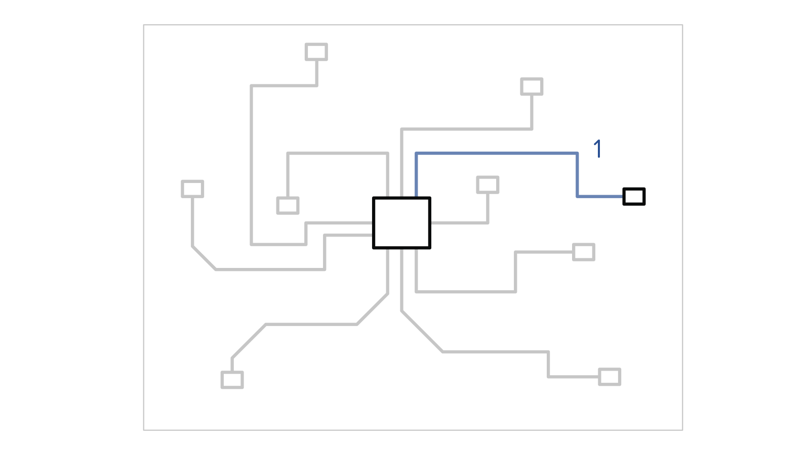
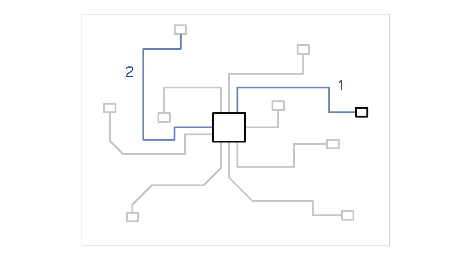
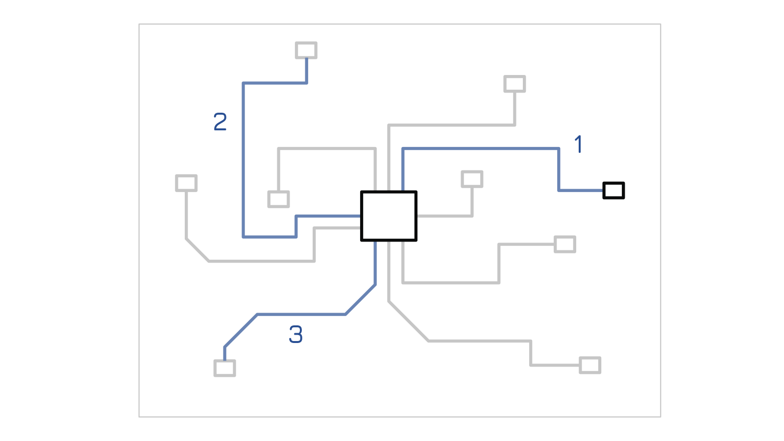
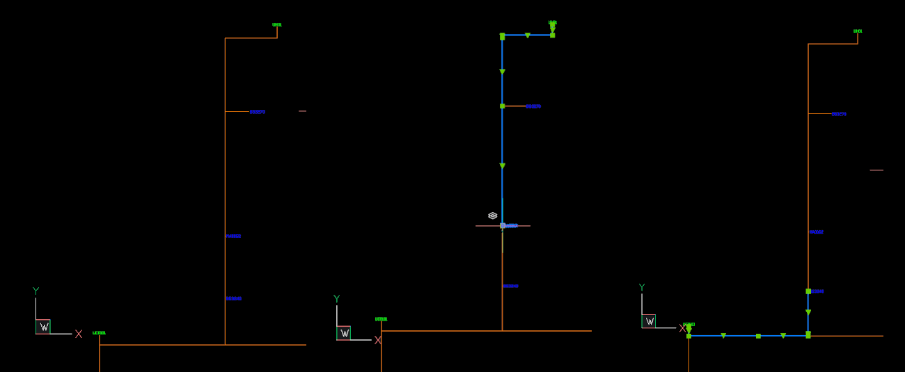
Extraction of equipment positions and all necessary cable lengths from DXF layouts. Created through pathfinding and automatic generation of optimal cabling.
Projekt
Automation in Cabling: Saving Time in Plant Planning
Kategorie
Electrical Design. Automation and Planning Department
Aufgaben im Projekt
Technologien
DXF, Python, Excel, ERP Integration
1/4
The cabling of large industrial plants is a complex process, as thousands of components are managed in a model. After completion of the planning, a parts list of all required sensors, actuators and cables must be derived from this layout. The necessary cable path must be determined and recorded in a list for each one. In the end, there is a list of the number of all required cables with the correct lengths, properly labeled and prepared for the construction site. All these steps were determined by measuring the line lengths in the CAD model and the positions of the associated sub-distributors or control cabinets.
2/4
Development of a tool that automatically determines cable lengths based on DXF-CAD drawings and documents them. The connection of sensors, actuators and sub-distributors is created via a graph. The derivation of all necessary further information into the existing ERP for easy ordering is the focus.
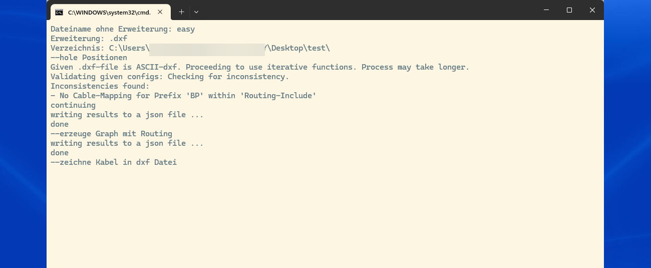
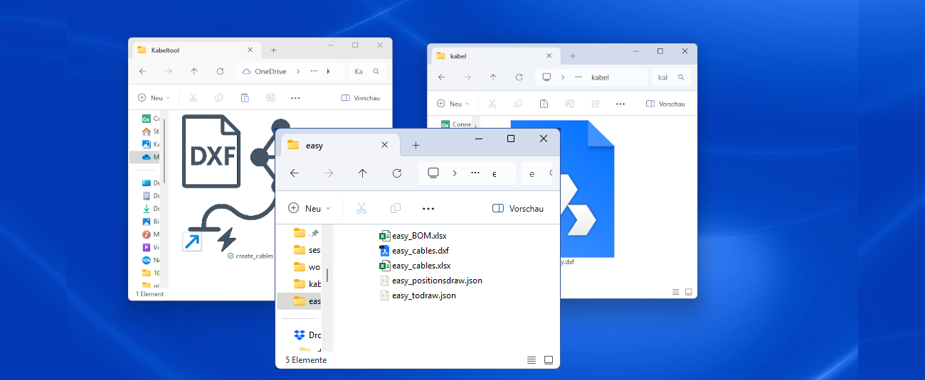
The tool reads DXF files, calculates cable routes automatically, and delivers Excel lists and DXF files with the cable paths for direct use. All processes are automated without user input.


3/4
The cable evaluation is based on a DXF file created by the automation department to represent the layout. The challenge was reliably detecting components such as actuators, control cabinets, and sensors and identifying their logical connections via polyline paths. A robust parsing logic was developed using defined symbols and geometric relationships to interpret the cabling and automatically generate cable lists.
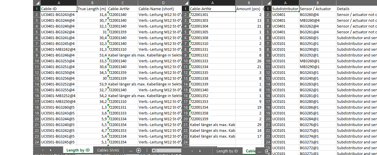
The tool-generated lists include not only source and destination points, but also ERP-relevant information like part numbers, connector types, and cable lengths. A direct ERP connection was prepared, but initially implemented via structured Excel formats. This allowed for manual verification and progressive automation.
For reliable operation, clear standards for layer names, symbols, and attributes had to be defined. A central symbol library and mandatory conventions ensured a unified data structure — essential for scalable use.
Cable evaluations, preparation lists, cutting lengths, and documentation overviews are all generated at the press of a button. Template-based layouts allow customer-specific formatting. An automated plausibility check detects issues like duplicate labels or open ends early on — without manual intervention. A comprehensive error report provides the possibility for manual correction within the layout.
Typical errors — such as unconnected lines, duplicate IDs, or incorrect layers — are automatically detected and logged in a dedicated error report. This prevents incomplete or inconsistent data from being used further. Errors are listed in a dedicated Excel worksheet for manual correction.
Clear documentation and process guidelines enabled fast adoption. Integration with existing Excel-based workflows ensured smooth acceptance across departments.

4/4
The time required from design to a ready-to-order assembly has been significantly reduced. Many error-prone, manual activities in the layout are eliminated – instead, automated workflows take over recurring tasks such as pathfinding, length calculation and parts list creation. The system is therefore not only a tool for evaluation, but a central element in the standardization of electrical engineering. It forms the basis for further digitalization steps in the entire product development process.

Michael Stangl
Managing Director